
Supports
Before we begin
Necessary Terminology
Extruder - This is a part of a 3D printer. This is the part that heats up to nearly melt the material so that the material can be worked with. A motor pushes the material through the hot part and out of a nozzle at the end.
Filament - This is the material that is extruded. In the case of buildIT, we use a Polylactic Acid (PLA) plastic filament. For more information, please see the post about materials.
Print Bed/Build Plate - This is a part of a 3D printer. This is the part of the printer that the filament is extruded onto. On some of our printers, this is a heated plate with or without glass on top. On others, it is simply a glass plate.
Layer Height - This is the amount the extruder moves vertically between each layer of the print. This number is usually a fraction of a millimeter for our printers. For more information, please see the post about layer heights and resolutions.
What are supports?
Technical Description
Supports are extrusions of material that are continuously built up to prevent droop for an object or a part of an object where previous layers are insufficient to prevent droop on their own. The 'rule of 45°' is often used to determine when supports are necessary. This rule will be discussed below.
Explanation
Plastic cannot be deposited onto thin air - it needs something to sit on. Supports are extra bits of plastic that are put down as the printer moves through the layers. They can be thought of as temporary scaffolding for the part; supports are for the construction of a part to help it be built and are removed when the part is done. Since 3D printing is done in layers, the scaffolding is built up layer by layer as the part is.
Supports are necessary when the object has overhangs. An overhang is a piece of an object that does not have a layer directly beneath it. In other words, to attempt to print an overhang would be like trying to print onto thin air - there's nothing for the plastic to sit on. Supports remedy this by providing a temporary structure for the object's overhangs to be printed on.
When should I use supports?
The 45 Degree Rule
There is a general rule of thumb for when parts need supports called the "45 degree rule." It may be hard to think about the 45° Rule on a 3D model or object, so this section explains the concept, and the next section has an example.
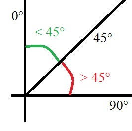
The image to the right shows a plane. The vertical axis is at 0°, there's a line in the middle at 45°, and the horizontal axis is the 90°. If the overhang of a part is between 0° and 45° from vertical (the green curve on the picture to the right), supports are unnecessary. If the overhang of a part is between 45° and 90° from vertical (the red curve on the picture to the right), supports are required.
A variation of this uses 60° from the vertical as the cutoff for needing supports. We use 45° because it tends to be the easiest to visualize, and it works very well for making sure that all parts that need supports have them.
An Example
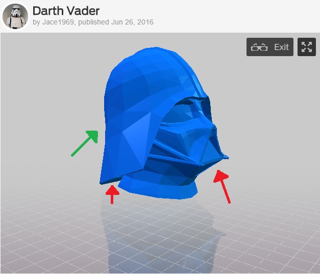
The image to the right is a screenshot of a model of a Darth Vader helmet by Jace1969 from Thingiverse. The arrows, two red and one green, point to three different locations where there is an overhang. These are not the only overhangs on this model, but they are the easiest to see.
The rightmost arrow is red. It points to a part of the object that doesn't have another part of the object directly beneath it, so it is an overhang, and it juts out from the part between 45° and 90° from vertical. This portion needs supports.
The center arrow is also red. It points to another overhang, This is also between 45° and 90° from vertical, so it also requires supports.
The leftmost arrow is green. The curve of the helmet is an overhang because there isn't another portion of the object directly beneath it. However, unlike the other two parts, this is between 0° and 45° from vertical, so no supports are necessary.
What do supports look like?
The Model
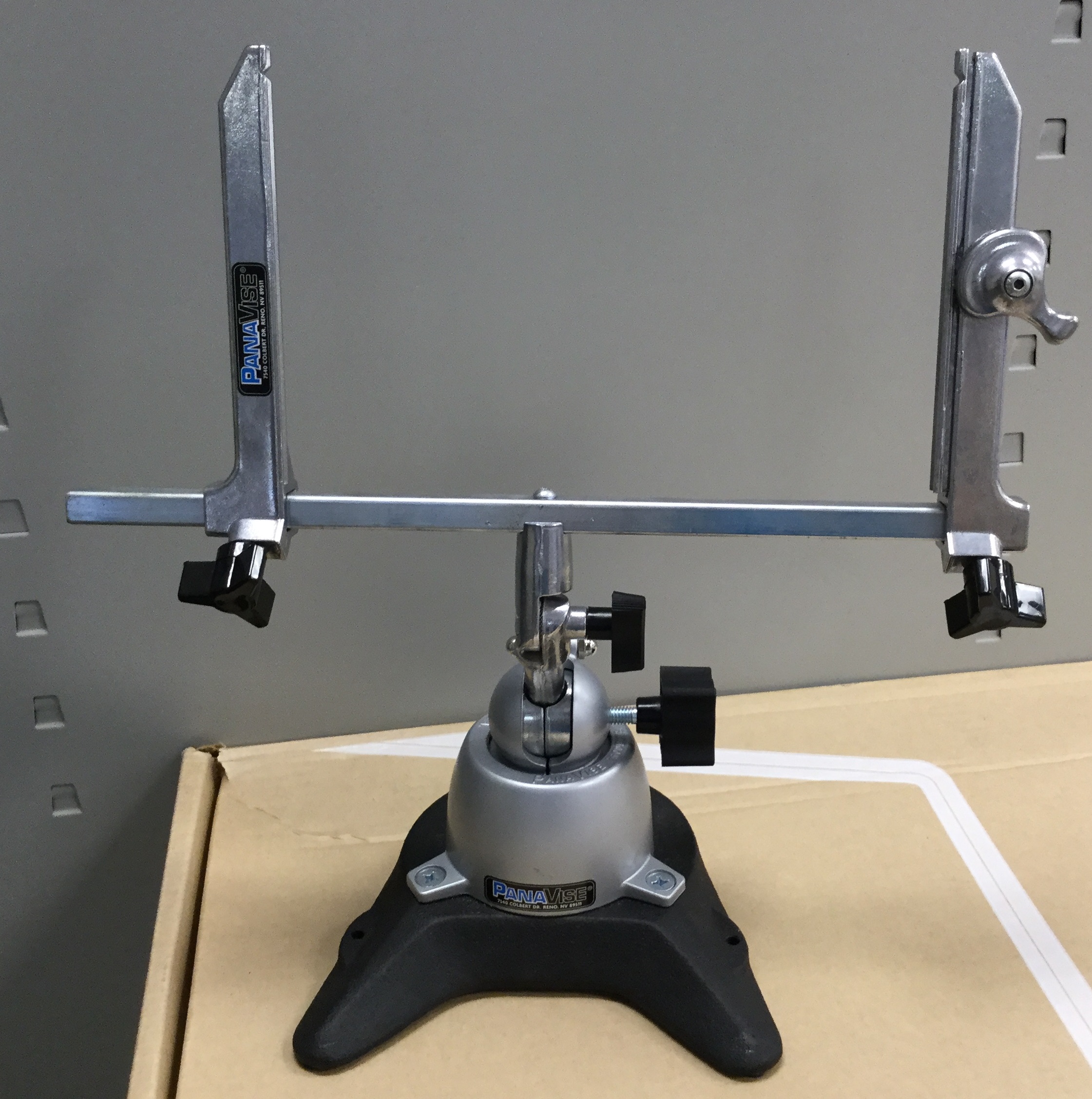
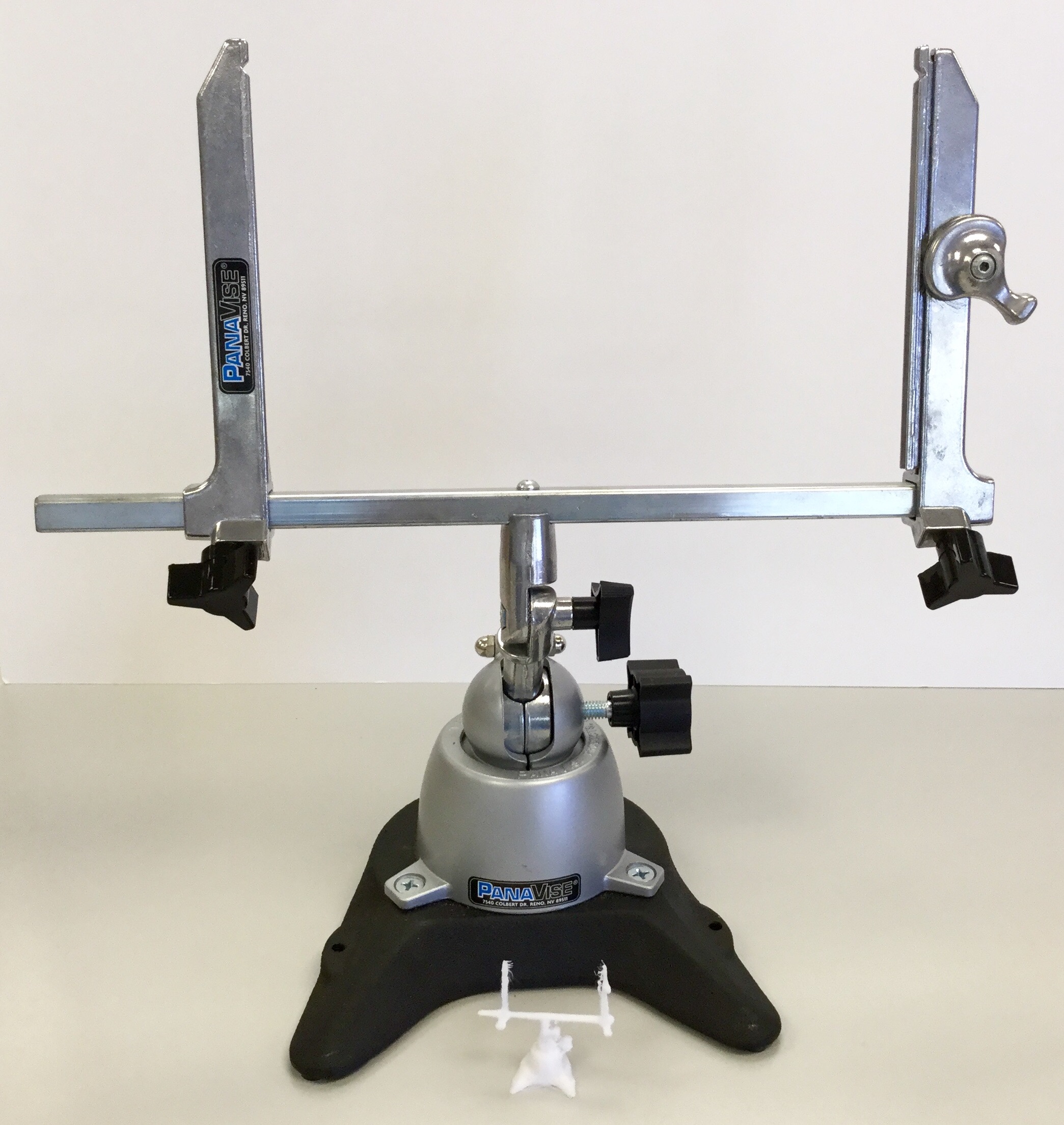
For this example, I decided to 3D scan a vice that we had on a workbench in buildIT. This is a picture I took of the model for our part.
For more information on 3D scanning, see our blog post about it!
Looking at the model, you'll notice that it has two arms at 90° to the vertical. This means that the printed version will require a lot of supports.
On the printer
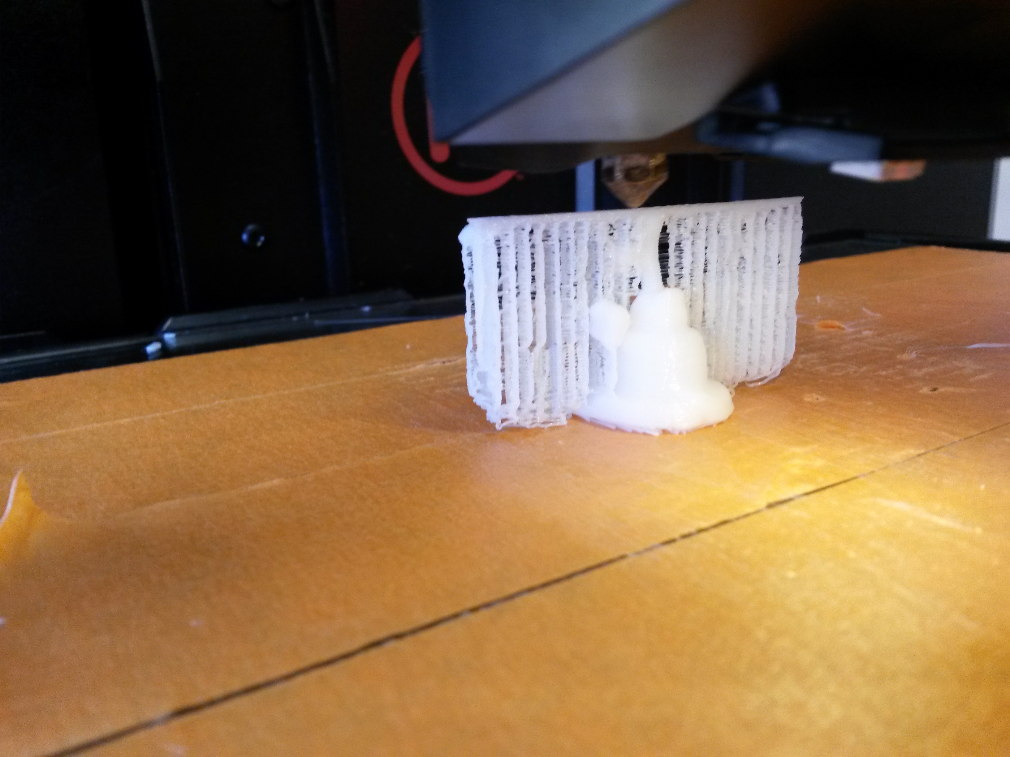
The small vice was printed on the Makerbot printer with supports. The print was nearly done by the time this picture was taken.
The supports are completely done. The thinner-looking extrusions all along the sides are supports. They are meant to snap off easily once the part is removed from the printer.
Off the printer, on the part
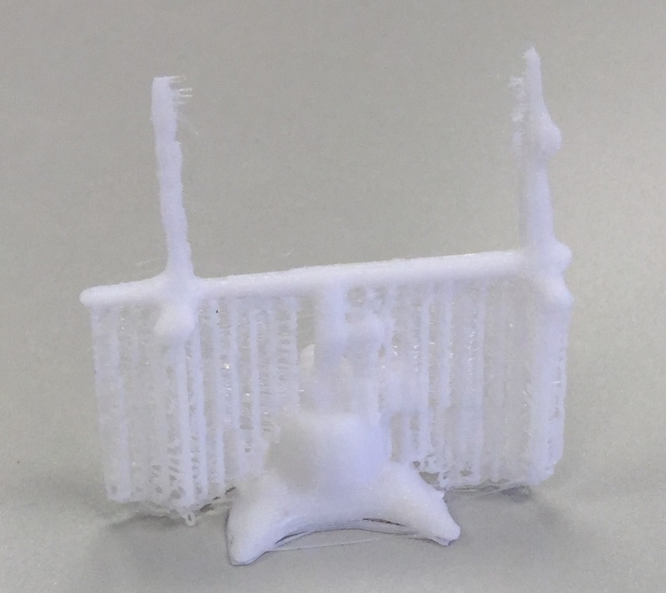
This is how the part came off the printer. The supports are attached to the part - they move when the part does. However, they are very thin.
At this stage, it should be very easy to remove them. This part was a bit of a challenge because of how thin the actual part is. The majority of parts will have something much more substantial than the supports staying on the part, whereas this part was about as thin as the supports were.
Off the printer, off the part
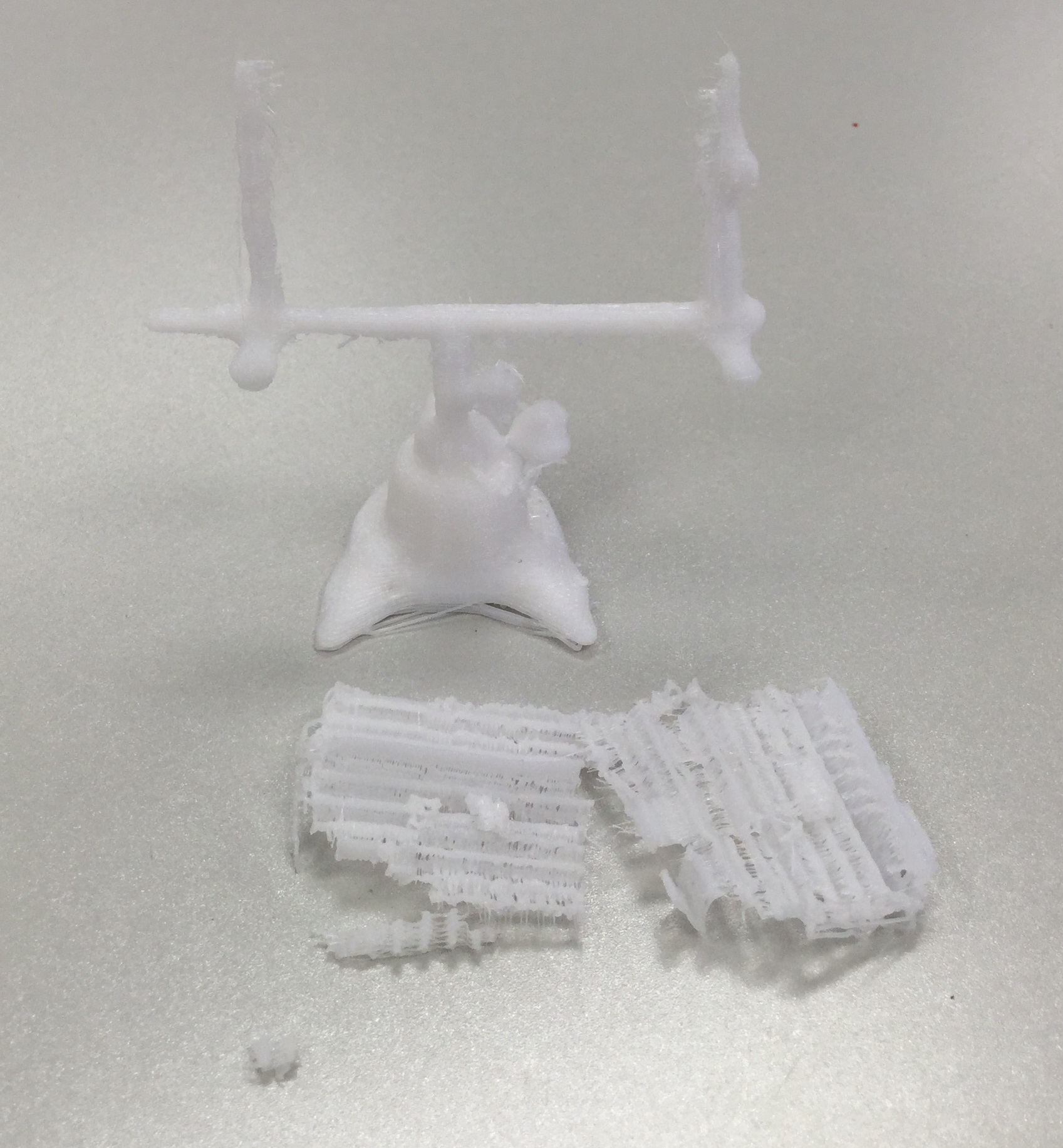
The supports have been removed. The part is ready to be cleaned up with a hobby knife to get rid of any other excess filament.
The supports are now trash. They can be thrown away in a trash can or in our plastic recycling can.
Remember to clean up after yourself!
Comparison
This picture shows the completed and cleaned 3D printed version of the vice in front of the model.
I think they look pretty similar!